1 General Features
The main update in version 9.4 is the ability to merge multiple crack remesh regions into
one. This improves the analysis of interactions between different cracks compared to
previous versions. For models using the remesh method for crack growth, the crack surface
area can now be viewed not only in the .rep file but also plotted in the x-y plot
post-processing function. Remesh regions can now include degenerate hexahedral elements. The
GUI encoding has been upgraded to better handle files containing non-ASCII characters.
1.1 Remeshing
1.1.1 Merging of Remesh Regions
In previous versions, the remesh regions for different cracks in a model could not overlap or
intersect. In version 9.4, when remesh regions for different cracks contact or intersect,
they are automatically merged into a new region. The merging process is fully automatic,
requiring no additional input from the user.
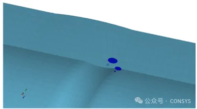
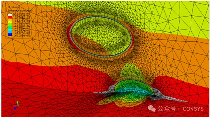
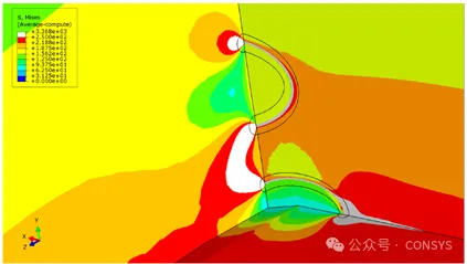
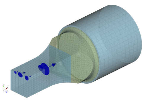
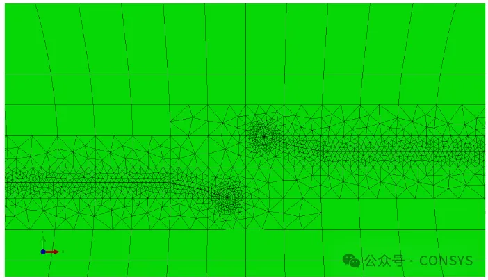
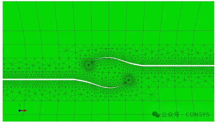
Modeling cracks close to each other is now easier, such as two cracks on a symmetry plane of
a welded pipe, as shown in Figure 1. Similarly, modeling the interaction or shielding
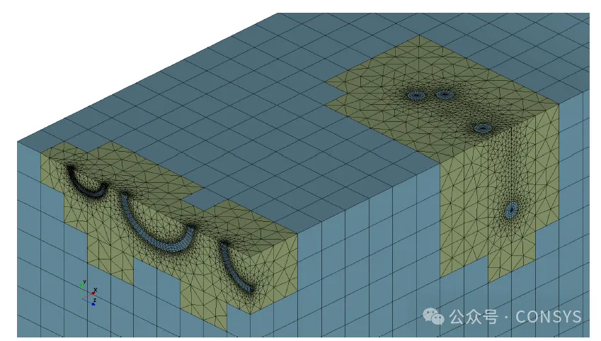
effects between cracks, such as three co-planar cracks sharing one remesh region, becomes
simpler (Figure 2)
Figure 1a: Co-planar buried crack and a surface crack
Figure 1b: Manually controlled tetrahedral mesh density
Figure 1c: Sectional view showing internal stress
Figure 1: Two cracks close to each other on the symmetry plane of a
welded pipe
Figure 2a: Initial positions of five cracks
Figure 2b: Mesh with cracks (two remesh regions)
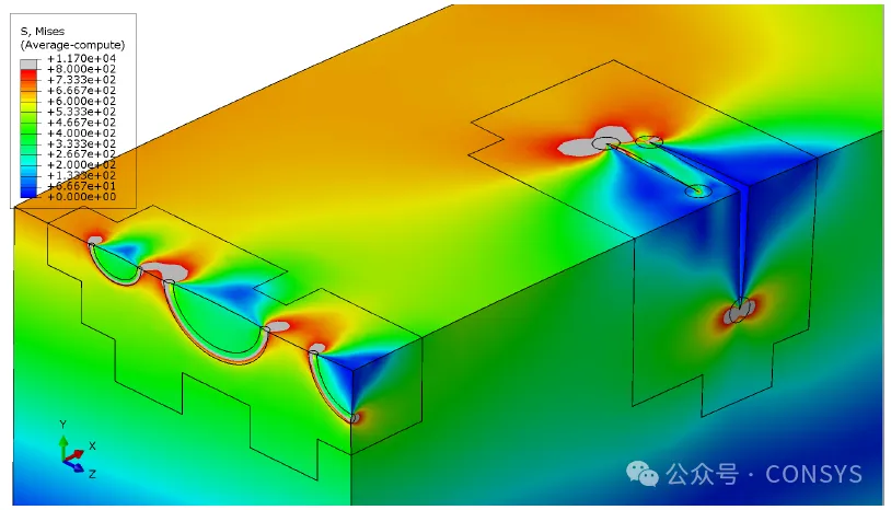
Figure 2c: Stress distribution reflecting interaction and shielding
effects
Figure 2: Interaction and shielding effects between multiple cracks
on a specimen with a square cross-section
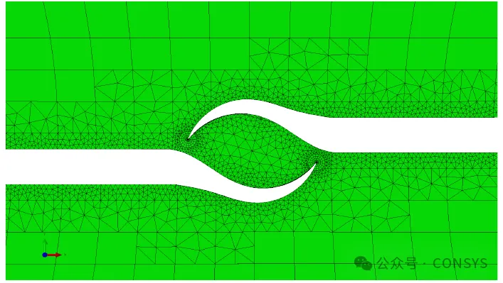
When cracks that initially have separate remesh regions eventually intersect during crack
growth, their remesh regions will also be merged automatically.
Figure 3: Merging of Remesh Regions During Crack Growth
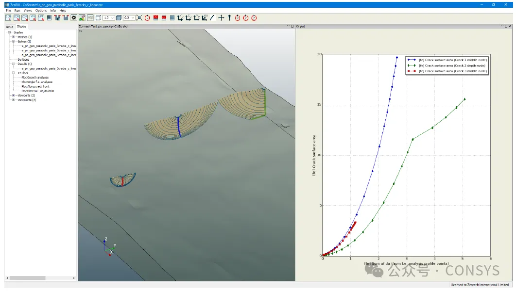
1.1.2 Calculation of Crack Surface Area
In version 9.4-1, the crack surface area for the remesh model is calculated and written to
the .rep file. It is also added to the list of variables for plotting in the GUI, allowing
users to plot crack surface area curves. The crack surface area is the sum of the areas of
all the elements on one side of the crack surface.
Figure 4: Example of Crack Surface Area Visualization
1.1.3 Degenerate Hexahedral Elements as Remesh Regions
Unlike previous versions, version 9.4 allows remesh regions to be fully contained within
degenerate hexahedral elements.
1.1.4 Tetrahedral Element Quality Check
Version 9.4-1 includes more checks for tetrahedral element quality during remeshing to avoid
generating poor-quality elements. The checking criteria have been aligned more closely with
Abaqus and Ansys. In previous versions, only a zero-volume check for Abaqus was performed,
but now additional checks have been introduced:
- Zero-volume check consistent with Abaqus tolerance: elements with volumes smaller than
10^-36 are considered to have zero volume.
- Zero-volume check consistent with Ansys tolerance: elements with volumes smaller than
10^-30 are considered to have zero volume.
- Abaqus shape factor check: elements with a shape factor smaller than 10^-36 fail the
check.;
- Ansys tetrahedral collapse check: elements with a collapse factor smaller than 10^-10
fail the check.
1.1.5 Enhanced Crack Surface Definition
In version 9.3, multiple cracks were defined as one surface. In version 9.4, each crack can
have its own crack surface, allowing different conditions such as pressure and heat transfer
to be applied to different cracks.
1.2 Zencrack GUI
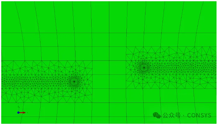
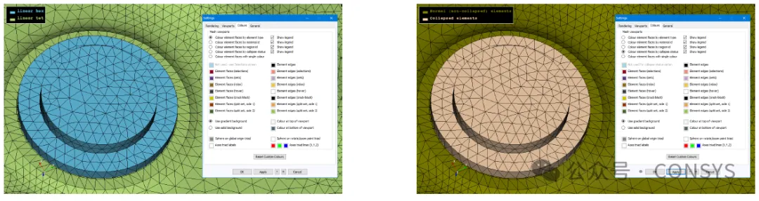
1.2.1 Display of Degenerate Elements
The GUI in version 9.4-1 introduces the ability to display degenerate elements.
Figure 5: Default Element Types Displayed by Color (Left) and
Degenerated State Display (Right)
1.2.2 Changes to Crack Front Node Coordinates, Sum of da, and Distance Along Coordinate Path
in XY Plot Functionality
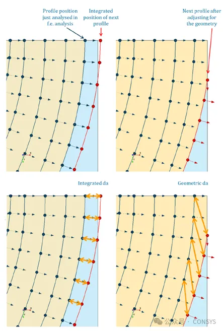
Version 9.4-1 changes the way crack front node coordinates are extracted and reported by the
process program. The node coordinates are now extracted after crack growth integration and
redistribution to ensure consistency with the geometric model, addressing an issue in
previous versions where node coordinates might fall outside the geometric model (see Figure
6).
Figure 6: Illustration of Different Definitions of da
Version 9.4-1 introduces two options for defining the sum of da:
- Sum of da (from integration): This was the default definition in previous versions and
continues in version 9.4-1.
- Sum of da (from geometric points): After crack growth integration, the software adjusts
node positions according to the geometric model. This new definition uses the adjusted
coordinates for the sum of da.。
The example in Figure 6 illustrates the potential differences that may arise between the two
different definitions in extreme cases.
In version 9.4-1, a new variable, "Distance along coordinate path," was introduced. This
variable calculates the accumulated distance of a specific node along the continuous crack
front position, similar to the "Sum of da (from f.e. analysis profile points)."
1.2.3 Other Changes
2 Abaqus Interface
- Updated support for Abaqus 2024, which now uses Python 3. Zencrack has updated the
zcr-odb.py file to correctly extract result data from Abaqus 2024.
- The keyabq.dat file has been updated according to Abaqus 2024.
- Enhanced handling of highly flattened tetrahedral elements.
- In the Remeshing model, the naming convention for crack surfaces has been changed from
the unified SURFACE_CRACKFACE to SURFACE_CRACKFACE_N for each individual crack surface.
3 Ansys Interface
3.1 Handling of Over-Constrained Models in Ansys 2024R1
Ansys 2024R1 changes the handling of over-constrained models, potentially introducing stress
hotspots near boundary conditions, an issue not present in previous versions. Version 9.4-1
addresses this issue to ensure that over-constraint does not occur when using the Ansys
2024R1 interface.
- (1) Applying Remeshing: On interfaces between loop elements and tetrahedral elements, or
between tetrahedral elements and surrounding elements.
- (2) Applying Crack-Blocks: On interfaces between Large Crack-blocks and surrounding
elements.
In 2024R1, there is a change in how over-constraints are handled. Testing has revealed that
hot spots of stress can occur at tie constraints near boundary conditions, which were not
present in earlier versions.
Version 9.4-1 addresses this issue to ensure that over-constraints do not occur. However, if
using older versions of Zencrack, caution is advised when using the Ansys 2024R1 interface.
3.2 Zencrack Updates
- The keyans.dat file has been updated for Ansys 2024 R1.
- The status value of the Ansys keyword KEYOPT has changed from 1 to 0; Zencrack can now
handle this keyword.
- The capability to handle flat tetrahedral elements has been enhanced.
- Issues with pressure update errors or transition elements being on incorrect faces when
using transition elements in the Ansys crack-block method have been resolved in this
version.
- In Remeshing models, the crack surface naming has been changed from the unified
SURFACE_CRACKFACE_SURF154 to individually defined SURFACE_CRACKFACE_SURF154_N for each
crack.
4 License
RLM installation now allows for the creation of a Windows service to run the license server.
5 Input Modifications
The output_code.dat file has been updated with new variable definitions and support for the
reduced variable axis list in the GUI. Additionally, some variable names have been changed:
- Sum of da has been renamed to Sum of da (from integration).
- Sum of da (f.e.step) has been renamed to Step of da (from integration).
- da X has been renamed to Step of da X component (from integration).
- da Y has been renamed to Step of da Y component (from integration).
- da Z has been renamed to Step of da Z component (from integration).
- New variable: Sum of da (from f.e. analysis profile points).
- New variable: Step of da (from f.e. analysis profile points).
- New variable: Distance along coordinate path.h
- New variable: Crack front length.
- New variable: Crack surface area.
Additionally, several other modifications have been made to change the curve plotting
functionality in the GUI:
- In the Along crack front curve plotting, "distance along crack front" can now appear on
the y-axis.
- In Along crack front curve plotting, the default x-axis label has been changed from
"distance" to "relative distance."
- In Single f.e. curve plotting, the x-axis label now includes a default value of "FE
time/load."
- A new domain for defining a reduced list has been added; variables in this domain will
appear in the GUI curve plotting window's reduced list of axis variables.
The subroutine user_dadn_sif has been updated to allow the sif-integral parameter as an
input.
Additionally, the Ini file has introduced new entries: